What is XDM : In this article, I will try to explain about XDM which is a important part of optical networking system. XDM is a single architecture that plays an important role in telecom networks. Some friends have suggested me to give information about XDM, so I am trying this. I hope that all of you will be satisfied with the information given.
Maybe you all know that XDM is a multiservice, high-density optical network platform and XDM capabilities including protection, services and management. Similarly EMS - XDM is an element management system in the telecommunications management network. Now I will further explain what is XDM?
What is XDM ?
XDM is a new generation optical networking system that integrates all functions of full point-of-presence (POP) into a single shelf-shaped element. XDM accommodates increased demand for bandwidth, while maintaining compatibility and enhanced flexibility for transport and routing all traffic types, including voice, data, and video.
The XDM’s single-architecture approach integrates the capabilities of multiple technologies – Dense Wavelength Division Multiplexing (DWDM), Time Division Multiplexing (TDM) and digital cross-connects (DXCs/DCSs) – and combines them into a single next-generation hybrid optical network element.
To handle the huge growth of data traffic, XDM also transports Internet Protocol (IP), asynchronous transfer mode (ATM) and Gigabit Ethernet (GbE) for efficient transmission of data.
Now we can say that XDM provides a wide variety of services, including:
◆ SDH interfaces: STM-1, STM-4, STM-16, STM-64
◆ SONET interfaces: STS-1, OC-3, OC-12, OC-48, OC-192
◆ PDH/Asynchronous interfaces: E1, E3, DS-3
◆ Data-aware interfaces: Ethernet, IP, ATM and SAN over STM/nc/STS-mc and transparent wavelengths
◆ DWDM
XDM Shelves
There are various XDM shelves, following is a short description of the various XDM shelves. XDM NEs can utilize one of the following shelf configurations:
• XDM -100 – miniature multiservice provisioning platform for metro-access and cellular networks
• XDM -200 – compact CWDM platform for metro-access and campus networks
• XDM -400 – Used for the compact MSPP for metro-edge or long-haul.
• XDM -500 – A compact shelf designed for medium interface capacities and outdoor installations, used as the data-aware access gateway
• XDM -1000 – Main purpose for multiservice metro optical switch and a standard shelf designed for high-capacity central exchange applications
• XDM -2000 – It is designed for pure DWDM applications as a multifunctional intelligent optical switch.
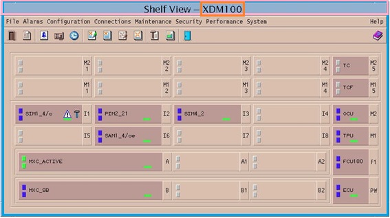
XDM-100 Shelf
The XDM-100 shelf consists of a single-row cage housing the I/O and processor cards, and a Tributary Protection Unit (TPU) above the shelf. Slot assignment is as follows:
• Eight slots (I1-I8) allocated to I/O interface modules.
• Two slots, A and B respectively, allocated to the MXC (Main Cross-connect) cards (main and protection). There are two slots (A1 and A2 and B1 and B2) in each MXC card that has to accommodate SDH aggregate modules.
• Eight slots allocated to the TPU modules.
• One slot (PW) allocated to the ECU (External Control Unit) card.
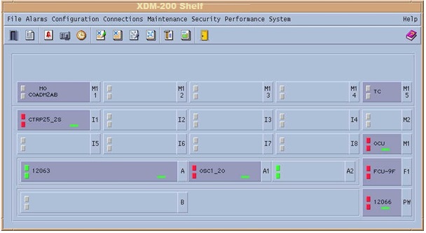
XDM-200 Shelf
The XDM-200 shelf is a derivative of the XDM-100 shelf that utilizes a
small-footprint CWDM technology to accommodate optical interfaces. Unlike the XDM-100, no TPU is available on the XDM-200 shelf. Slot assignment is as follows:
• Eight slots (I1-I8) allocated to I/O modules
• One slot (A) allocated to the MXC card
• One slot (PW) allocated to the ECU card
• Four slots allocated to Optical CWDM Unit (OCU) modules.
XDM-400 Shelf
The XDM-400 shelf consists of a single-row cage housing the I/O, matrix, processor and common cards. The shelf also includes two xINF4 and one xFCU4 units (containing five separate fans). Slot allocation is as follows:
• Five slots (IS1-IS5) allocated to I/O cards
• Two slots (X1 and X2) allocated to the matrix cards
• For the xMCP cards allocated two slots (C1 and C2).
• Two slots (MS1/Line1 and MS2/Line2) allocated to electrical interface connection modules.
XDM-500 Shelf
The XDM-500 shelf consists of a single-row cage housing the I/O, matrix, processor and common cards. The electrical interface connection modules and DWDM/OADM modules are housed in the central modules area. The shelf also includes two xINF and three xFCU units. Slot allocation is as follows:
• Six slots (IC1-IC6) flexibly allocated to I/O cards and/or transponders
• Four slots (MC1-MC4) allocated to electric interface connection modules or DWDM/OADM modules
• Two slots (X1 and X2) allocated to the HLXC matrix cards
• For the xMCP cards allocated two slots (C1 and C2).
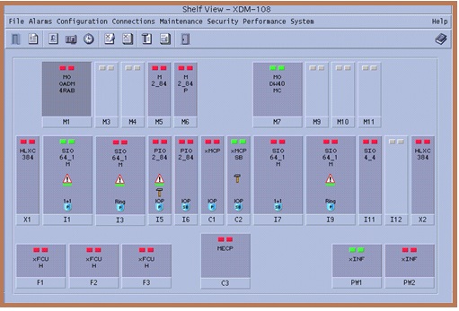
XDM-1000 Shelf
The XDM-1000 shelf is comprised of two cages. The cards (lower) cage houses the I/O, matrix, processor and common cards. The modules (upper) cage houses the electrical interface connection modules and DWDM/OADM modules. The shelf also includes two Input Power Filter Units (xINF) and three Fan Control Units (xFCU). Slot allocation is as follows:
Cards cage
• 12 slots (I1-I12) flexibly allocated to I/O cards
• Two slots (X1 and X2) allocated to the HLXC matrix cards
• For the xMCP cards allocated two slots (C1 and C2).
Modules cage
• For the electric interface connection modules or DWDM/OADM, optical booster and optical preamp modules allocated 11 slots (M-IO1 to M-IO11).
XDM-2000 Shelf
The XDM-2000 shelf consists of a single cage containing two slots for mux/demux cards and/or HXLC cards; 12 slots for transponders, optical fiber amplifiers and other optical modules; and two slots for the xMCP cards.
The external connection module MECP is located in the upper section of the cage.
International mechanical standards and specifications of XDM-2000 shelf design and mechanical practice conforms to . the slot assignment is as follows:
• For the transponders and other optical modules allocated 12 slots (I1-I12)
• For mux/demux cards or for the matrix HXLC cards (depending on the system’s configuration) allocated two slots (X1 and X2).
• For the xMCP cards allocated two slots (C1 and C2).
XDM Cards
XDM cards come in various widths, with the narrowest card occupying a single slot and the widest occupying four slots. Below describes the XDM card types.
Card Type HLXC and HLXC384 : Hi-Lo Cross-connect Matrix Cards (HLXC), one on each side of the cards cage. The HLXC receives/transmits aggregate streams and performs multiplexing, demultiplexing, cross-connect and node synchronization functions. The HLXC card includes TMU and TG objects. Both HLXCs operate simultaneously in a 1+1 protection configuration. The HLXC384 is an enhanced matrix card.
Card Type xMCP : It is called the Main Control Processor (xMCP) cards, it perform the XDM’s communications, control, alarm and maintenance functions. If any additional xMCP card may optionally provide full 1:1 protection capability. This card contains the NVM and COM modules. When installed in redundancy configuration, the xMCP cards are synchronized automatically every predefined time period or manually, via an EMS-XDM command.
The Main Control Processor (xMCP) card performs the XDM communications, control, alarm and maintenance functions. This card contains the NVM and COM modules. A redundant xMCP card may optionally provide full 1:1 protection capability at the equipment level. Upon failure of the active xMCP, the standby xMCP becomes the active control unit. The xMCP cards are installed in the two center slots of the cards cage, C1 and C2. The primary xMCP is installed in slot C1, and the backup xMCP is installed in slot C2.
Card Type MECP and MECPO (optical) : This card manages the two xMCP cards and provides equipment protection to I/O cards. This card used for the connecting the network management, Orderwire (OW) and overhead access (OHA) interfaces to the activate the xMCP card.
Card Type xFCU : This card used for the cooling unit.
PDH Input/output (PIO) Cards : Provides PDH I/Os. The name of the card is indicative of the number of PDH tributaries supported, the data bitrate supported and other protocol-related information.
SDH Input/output (SIO) Cards : Provides SDH I/Os. The name of the card is indicative of the number of SDH tributaries supported, the data bitrate supported and other protocol-related information. Cards with an M suffix are enhanced cards with QSP-NA support.
Ethernet Interface Switch (EIS) Card : Acts as an embedded Ethernet switch to provide Ethernet Layer 2 services in mixed SDH/SONET and Ethernet networks.
Data Input/output (DIO) Cards : The DIO cards provide an interface for Gigabit Ethernet (GbE) connections over the SDH/SONET network in XDM systems.
XIO Card : It is used as a Matrix card with I/O ports.
IO Modules : Input/output (IO) modules, inserted in the XDM modules cage, provide the electrical connectors for electrical PIO and SIO cards. The name of the card is indicative of the type of card it supports. A P suffix indicates that the module corresponds to a protecting card in the IOP scheme.
ATM Traffic Switch (ATS) Card : An ATM switch specifically designed to meet the requirements of 3G cellular networks.
Mux/Demux modules VMUX : Multiplexes optical channels (lambdas) into a DWDM optical signal and demultiplexes a DWDM optical signal into a number of optical channels. The Variable Mux (VMUX) card is a controllable mux that extends the length of the network by improving Optical Signal-to Noise Ratio (OSNR), equalizing gain tilt and adjusting the power of the added channels.
Transponders : The role of a transponder within an optical network is to provide the adaptation for a client signal into the network. Transponders support SDH/SONET, PDH/Async, ATM, IP and GbE at any bitrate ranging from 50 Mbps up to 2.5 Gbps and 10 Gbps. This adaptation requires a number of features, which are:
• Wavelength translation (accept any wavelength within the specified band, transmit on a specified wavelength)
• Bitrate adaptation
• 3R functions (Re-amplification, Reshaping and Retiming) of the client signal
• FEC encoding of the client signal.
MO_PAC MO_BAC : These card used as a Preamplifier and booster.
OFA : The Optical Fiber Amplifier is a card that can accommodate two channels or ports. They can be configured as booster, amplifier and/or inline amplifier.
OPM : The OPM card is a measurement instrument. It is comprised of an OPM measurement module and a 4:1 optical switch.
OADM : The OADM is a component that can drop and add a number of optical channels (wavelengths) G.692. It can add and drop single or multiple channels, at specific nodes, without interfering with the remainder of the pass-through channels. It therefore allows sharing network resources among several traffic hubs, nodes or sub-networks.
ALS : This unit Performs line protection and IO protection at the optical level.
Basic Principles of XDM Power Control
Below principles that apply for XDM power control.
Detecting span loss changes
A very reliable mechanism is implemented to detect a change in the span loss that may cause a change in the incoming power. This mechanism is the same in all cards (OADM, VMUX, OFA-2 and OFA_M).
Each card has means for measuring the incoming total power (a photodiode). The card is configured with a set of parameters with which it can calculate the expected total power. This is a function of the present updated number of active channels (NOC), their Power per Channel (PPC) and the actual number of previous amplifiers (NOA), for determining the total power of noise in the line.
The card’s software compares the actual incoming power with the expected power and monitors the difference. As long as the number of channels and number of amplifiers are updated, the comparison reflects the exact changes in span loss when there are any. Updating the NOC and NOA is not done automatically at present. For each card, the NOC and NOA at its output is calculated, taking into account the incoming NOC, NOA and LOS condition, as well as its add and drop channels, if any.
Actions for span loss changes
OADM cards and VMUX cards operating in OADM mode change the power of the added channels to track the changes of the span loss in order to keep the same power per channel for all channels (added and passed-through).
Generally, upon detection of a change in the span loss, the amplifiers compensate for it in order to return to the original network design, by changing their overall gain.
If the span loss increases, the OFA is requested to increase its gain; if the span loss decreases, the gain is decreased too. In both cases, the principle whereby gain equals previous span loss applies.
Calculating the expected incoming total power
Each card involved in the leveling process can be located at a different distance (in terms of loss of spans in dB) with a fixed duration between different amplifiers. Since at the output of the amplifiers the PPC is fixed, this is a good point to relate to. Thus, the calculation for the expected incoming power is made first for the output of the last amplifier before the subject card, and then the span loss from the last amplifier’s output until the photodiode of the subject card is subtracted.
Required correction decision mechanism
In order to prevent frequent reactions to changes, a threshold limit has been defined called Tracking Tolerance. Any changes in span loss below this threshold are not taken into consideration. Thus, minor changes in incoming power do not cause any reaction. Another threshold is called the Tracking Limit. Changes above this limit are also ignored.
To prevent untimely changes in the chain of elements down the line, and thus prevent oscillations, there is a Holdoff Time (HOT) period. The total HOT of an element is the original HOT (configuration) multiplied by the number of preceding elements. The latter is the total number of reacting elements that precede the current element upstream.
Card behavior algorithm
When there is a change between the tolerance and the tracking limit, it causes the tracking mechanism to adjust the power level of the added channels in an OADM or VMUX, and the gain of an OFA, in order to compensate for the difference.
If the power at input decreases following an increase in the span attenuation (loss), the OADM or VMUX decrease the power of the added channels to bring them in line with the incoming channels that are also going through, thus equalizing the output spectrum. This obviously brings down all the channels that proceed to the next hop. Since it is desired to keep a constant power budget throughout the network, the OFA located after such an OADM increases its gain, thus restoring the power per channel at its output to the previous level.
Network Setup
Network setup divided into three phases:
• Setup of limiting parameters. These parameters determine the tracking mechanism operating range and activation delay time. These parameters include:
• Tracking Tolerance (recommended = 0.5 dB)
• Tracking Limit (recommended = 3 dB)
• Previous Spans Number – according to position
• Total HOT
• Set-up of the basic required gain, power or attenuation, and the respective offsets as implemented (differently in the OADM, OFA or VMUX). These are the baseline for the expected output power per channel that must be kept either constant (OFA) or aligned to the incoming power (OADM or VMUX).
Incoming power monitor
For tracking purposes, the power of the incoming signal (to the NE) must be measured, exactly like in the OFA and OADM cards. However, unlike the OFA and OADM, the VMUX does not interface with the incoming line and is thus unable to measure the incoming power.
The demux card at the opposite side has an additional, dedicated output of a 2.5% or 5% sample of the incoming power (this rate may vary between different types of demux cards). It is connected by an optical fiber to the VMUX, where it is connected directly to a photodiode for power measurement. To calibrate this measurement, the Mon percentage in the VMUX is used. The value is taken from the Demux Info View.
OFA cards (OFA-2 and OFA_M)
OFA cards have a configurable gain, with each card having a certain gain range. The required gain at any moment is the sum in dB of the Base Gain and the required correction, as described in Power Control Object Attributes, page 7-61. The Base Gain can be set manually, or it can be calculated automatically using some configured parameters/attributes. The operation scenarios of the OFA cards include the following use cases:
• Span loss change
• Fiber cuts
Last Word
Dear friends, I have tried my best to give complete information about XDM, but it is not possible to give complete information about XDM in one article. Important points of XDM are explained. If you want more information, write me the points you want to know about. How did you like this article " What is XDM "? Please tell me by commenting. If considered appropriate, then share it to your friends too.


0 Comments