FTTH Infrastructure Sharing : This article will cover the how to Share Infrastructure of FTTH Network. Today I will describes the basic and general concept of FTTH Infrastructure sharing for the neighborhood.Due to the high costs of FTTH deployment, cooperation of fiber and infrastructure networks has been hotly discussed by interested parties. In addition, regulatory bodies are closely observing activities in this field with the aim of encouraging a competitive environment thus avoiding monopoly situations.
There are various “layered” FTTH business models operating in the market today; this has paved the way for non-traditional telecom operators to become involved in this sector. These include utility providers, municipalities, real estate developers and governments, all of which are looking for the optimal way to deliver fiber to the ho)me.
FTTH Infrastructure Sharing for Green Field include below important parts-
(A) FDT to Fiber Access Terminal (FAT)
(B) FAT to customer boundary wall
Trenching and duct configuration also required for the sharing of FTTH network between FAT to customers boundaries. Generally two trenching size suggested for the same. First is the 15x65cm and second trenching size is the 15x50cm. Duct configuration depend upon the company configuration.
Duct Material and Supplier also a important part for the sharing of FTTH network. Generally used 50mm HDPE (High density Poly Ethylene) duct with 2-20mm built-in duct inside 50mm. It is important that both operators will make sure the availability of multi local suppliers for duct. The minimum requirement of duct shall be PE-100/PN16 (Pressure 16 bar) and the minimum internal diameter 18mm.
4x 110mm and 12x50mm opening will be provided on two walls and 4x110mm will be provided on other two walls for the duct entry and exit. Must be install the cover of the handhole will be of heavy duty with minimum 40 ton loading. The common company logo for both parties shall be agreed to be on every Handhole cover. Each party will install maximum one joint closure in one handhole.
The all agreed rules and concept of both party will be reviewed after every six months based on the experiences during implementation to make it more efficient and practical.
Brown filed is where the operator has existing FTTH network and deployed before the sharing concept. As buit drawing shall be handed over to the other party for design analysis.
Fiber Distribution Terminal (FDT) to Fiber Access Terminal (FAT)
Availability of spare duct
The owners will hand over two ducts/subducts and with an option to have additional one more Duct/subduct based on the existing configuration and the demand of the visiting operator.
Non available spare ducts
The owner will trench only those portions where spare ducts/subducts will not be available. Owner will reinforce existing duct or trench parallel to existing to fulfill the requirement of visiting operator.
This case will be very rare and expecting only 10%-15% in the existing infrastructure.
FAT to Customer boundary wall
➤Availability of spare ducts
The owner will hand over one ducts/sub-duct to the visiting operator.
➤Non available spare ducts.
➥Existing duct with no cable installed: The owner will install two micro ducts (12mm OD) in existing one 32mm (OD) duct and will be shared between owner and visiting operator.
➥Existing duct with cable installed: Existing duct of 32mm OD with cable up to 4 fibers; another cable of maximum 8F will be installed by visiting operator with full precaution and coordination with the owner making sure not to disturb the running services.
Existing duct of 32mm OD with cable more than 4 fibers; the owner will reinforce the duct and will hand over one duct to the visiting operator. This case will be very rare and expecting only 10%-15% in the existing infrastructure.
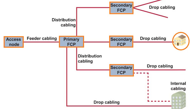
For each of these models, infrastructure has to be shared. There are four methods of infrastructure sharing between the telecom operators, ranging from passive to active components of the network:
Process of FTTH infrastructure sharing
We usually divide FTTH infrastructure sharing into two part (1) FTTH Infrastructure Sharing for Green Field. (2) FTTH Infrastructure Sharing for Brown Field.Now we will discuss this in details-FTTH Infrastructure Sharing for Green Field
FTTH Infrastructure Sharing for Green Field include below important parts-
(B) FAT to customer boundary wall
(C) Hand hole
(A) Fiber Distribution Terminal (FDT) to Fiber Access Terminal (FAT)
Trenching and duct configuration required,The trench size will be depend upon the local area condition and company specifications. The duct placement and backfilling details also provided by the telecom operator. Generally the developer duct will be in bottom in their respective areas.
Spacers will be installed with the duct at every 1.5m to keep the duct straight and in position.If more than two ducts will be required in the trench for access network, the developer will submit the detail design. Duct Material and Supplier depend upon the company agreement. Mostly used for the sharing is that 110mm PEC (Poly Ethylene Corrugated) duct with 5-32mm built-in duct inside 110mm and also used 110mm HDPE (High Density Poly Ethylene) duct with 5-32mm built-in duct,
(D) Installation of FDT
(E) Design Approval Process
(F) Updating FTTH Infrastructure Design Concept Document
(F) Updating FTTH Infrastructure Design Concept Document
Trenching and duct configuration required,The trench size will be depend upon the local area condition and company specifications. The duct placement and backfilling details also provided by the telecom operator. Generally the developer duct will be in bottom in their respective areas.
Spacers will be installed with the duct at every 1.5m to keep the duct straight and in position.If more than two ducts will be required in the trench for access network, the developer will submit the detail design. Duct Material and Supplier depend upon the company agreement. Mostly used for the sharing is that 110mm PEC (Poly Ethylene Corrugated) duct with 5-32mm built-in duct inside 110mm and also used 110mm HDPE (High Density Poly Ethylene) duct with 5-32mm built-in duct,
(B) FAT to customer boundary wall
 |
| FTTH Infrastructure FAT to customer boundry |
Duct Material and Supplier also a important part for the sharing of FTTH network. Generally used 50mm HDPE (High density Poly Ethylene) duct with 2-20mm built-in duct inside 50mm. It is important that both operators will make sure the availability of multi local suppliers for duct. The minimum requirement of duct shall be PE-100/PN16 (Pressure 16 bar) and the minimum internal diameter 18mm.
(C) Hand hole
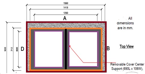
Generally two cover handhole is suggested to install in FTTH access network. The size will be depend upon the company but maximum telecom operators used the "Outer dimension: 155(L)x100(W)x95(H)cm" and Inner Dimension : 125(L)x 80(W)x(80H)cm hand hole.
 |
| FTTH Hand hole infrastructure sharing |
Generally two cover handhole is suggested to install in FTTH access network. The size will be depend upon the company but maximum telecom operators used the "Outer dimension: 155(L)x100(W)x95(H)cm" and Inner Dimension : 125(L)x 80(W)x(80H)cm hand hole.
(D) Installation of FDT
The developer scope of work will be limited to installation of concrete base only. FDT/ FSC concrete base shall be installed by developer for both parties. Each party will provide the design drawings of concrete base with specifications and also the approved supplier list. Developer will install 2x110mm duct from the nearest Access Network Handhole to each FDT/FSC base
The developer scope of work will be limited to installation of concrete base only. FDT/ FSC concrete base shall be installed by developer for both parties. Each party will provide the design drawings of concrete base with specifications and also the approved supplier list. Developer will install 2x110mm duct from the nearest Access Network Handhole to each FDT/FSC base
(E) Design Approval Process
The developer will prepare the detail design of the assign district and will submit to other party for the approval. Other party will make his approval or comments if any, within five working days.If there is no comment on the design or did not receive formal approval within agreed SLA, then it will be assumed as approved. The developer will announce it as approved.
The developer will prepare the detail design of the assign district and will submit to other party for the approval. Other party will make his approval or comments if any, within five working days.If there is no comment on the design or did not receive formal approval within agreed SLA, then it will be assumed as approved. The developer will announce it as approved.
(F) Updating FTTH Infrastructure Design Concept Document
FTTH Infrastructure Sharing for Brown Field
Brown filed is where the operator has existing FTTH network and deployed before the sharing concept. As buit drawing shall be handed over to the other party for design analysis.
Fiber Distribution Terminal (FDT) to Fiber Access Terminal (FAT)
The owners will hand over two ducts/subducts and with an option to have additional one more Duct/subduct based on the existing configuration and the demand of the visiting operator.
Non available spare ducts
The owner will trench only those portions where spare ducts/subducts will not be available. Owner will reinforce existing duct or trench parallel to existing to fulfill the requirement of visiting operator.
This case will be very rare and expecting only 10%-15% in the existing infrastructure.
The owner will hand over one ducts/sub-duct to the visiting operator.
➤Non available spare ducts.
➥Existing duct with no cable installed: The owner will install two micro ducts (12mm OD) in existing one 32mm (OD) duct and will be shared between owner and visiting operator.
Existing duct of 32mm OD with cable more than 4 fibers; the owner will reinforce the duct and will hand over one duct to the visiting operator. This case will be very rare and expecting only 10%-15% in the existing infrastructure.
FTTH Infrastructure sharing
For each of these models, infrastructure has to be shared. There are four methods of infrastructure sharing between the telecom operators, ranging from passive to active components of the network:
DUCT: Many retail or bulk service providers can share the usage of a duct network, either through drawing or blowing their fiber cable into a sufficient area. They then compete with one another on the available services.
FIBER: Telecom service providers can use the FTTH network by connecting to the physical layer ("dark" fiber) interface and compete with one other on available services.
Access to fiber can be granted at various points in the network: at the central office or POP or at some place between the building and the central office or in the basement of an MDU.
This point is known as the fibers flexibility point (FFP) and is the location point where the
various service providers gain access to the subscribers.
A PON service provider may install splitter(s) at these FFPs and backhaul the traffic over a
reduced number of feeder fibers to the POP.
A Point-to-Point service provider may install Ethernet switch(es) at these FFPs and backhaul the traffic over a reduced number of fibers to the POP, or alternatively install a cross-connect and connect his subscribers to the POP using a number of fibers equal to the number of subscribers.
WAVELENGTH: Telecom service providers may use the FTTH network by connecting at a wavelength layer interface, and compete with one another on available services.
PACKET: Telecom service providers may use the FTTH network by connecting at a packet layer interface, and compete with one another on available services.


0 Comments