Similarly, if the service is VoIP or Internet service, testing with a Layer 1 Bert, a Layer 2 throughput test, or a Layer 3 Ping might still not be enough. Think of what the service involves. VoIP is a phone service and is used to place calls, and Internet service is used to view web pages. Therefore even if tests at Layer 1 to Layer 3 are successful if you can not place calls with VoIP or view web pages with Internet service the service is not working properly.
 |
| Where to test Ethernet |
Ethernet Protocol Functions
The protocols are usually structured together to form a layered design (also known as a "protocol stack"). All major telecommunication network architectures currently used or being developed use layered protocol architectures. The precise functions in each layer vary. Protocol function will be very clear with the help of below details-
 |
| Ethernet Protocol Function |
➥Layer 1 BERT
➥Layer 2 BERT
–Constant
–Burst
–Ramp
➥Vlan Testing
➥Priority Testing
➥Streams
➥Loopbacks
➥RFC 2544
➥Service disruption recovery time
➥Measuring Round Trip Delay
When testing an Ethernet service or Ethernet link different options exist. Choosing the right test is dependent on the type of service. Tests range from Layer 1 BERT tests to Layer 1 through Layer 7 network monitoring and protocol analysis. Properly optioning the test set is important to have the most relevant results.
Layer 1 BERT, Layer 2 BERT and Throughput testing, Vlan Testing, Priority Testing, Using streams, Loopbacks, testing with RFC-2544, Measuring service disruption recovery time and Measuring round trip delay.
Analyser And Switching
➥Direct connection to a port.
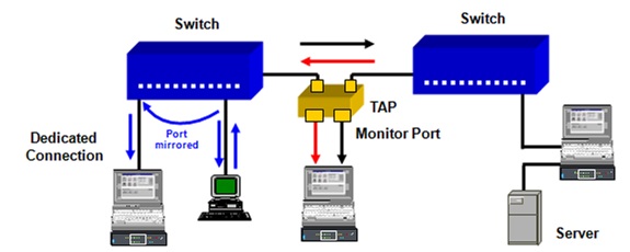
➥Connection to a Mirror port (Configurable Monitor Connection)
➥Loop into an existing connection.
➥Direct connection to a port.
➥Connection to a Mirror port (Configurable Monitor Connection)
➥Loop into an existing connection.
 |
| Analyser ans switching in Ethernet Testing |
In purely switched networks, “shared media areas” no longer exist. The complete network technology consists of layer 2 switches. Each terminal is dedicated to one switch port. The data flow at the switch takes place between the input and output port of the involved communication partners. An analyser connected to the switch port would not, however, recognize the connection.
A switched network can be divided into three error sections: the network, the terminals (client / server) and the application. To enable monitoring and to analyse error sections network analysers placed at the right location carry out network analysis and statistics.
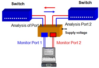
The data flow becomes transparent by looping it through the analyser, when the connection is looped. Both receivers of the analysers are decoupled and connected to full duplex connections. Each receiver monitors transmission in one direction. The monitored link is interrupted once.
The analyser should be equipped with two separate receivers. This is not the usual case with software analysers. It is based on a network card (NIC) placed in a PC. The NIC is designed for one terminal and is therefore only equipped with one receiver. Even a NIC, which supports the full duplex mode, can not be looped into a dedicated connection.
➥Full duplex
- no collisions
- no erroneous frames
- Broad cast multicast frames
- Non-learned Unicast frame.
 |
| Measurement at switch in Ethernet Testing |
In a purely switched network environment physical errors are restricted. A rapid way to prove whether they exist or not, is through a printout of the error counters for each switch port. Usually only the broadcast and multicast packets are shown.
Individual unicast packets of those stations not entered in the switching table are the only ones identifiable.
Collisions, fragments or physical errors are not forwarded to other switch ports. Problems of individual users are restricted to the client-switch port connection and do not effect other users.
 |
| Ethernet Mirror port |
The monitor port, or a mirror port needs to be configured. Too configure this type of port on the Ethernet switch interfaces which have traffic to be monitored are selected and a mirror port is also selected. Then the traffic entering and exiting the selected interfaces is going to be replicated or “mirrored” out the mirror port. If working with popular Cisco switches the term SPAN port is used.
A switch port e.g. a 100BaseTX can indeed be operated in a full duplex mode. Its monitoring capacity as a mirror port is however only 100Mbit/s. This means only a cumulative bandwidth of 100Mbit/s can be mirrored. Consequently, if on both lines of a mirrored full duplex connection, more than 100Mbit/s (the sum of both lines) are transmitted, a problem with the bandwidth may result. If this up-link is loaded with more than 100Mbit/s, not all packets at the monitor port will be visible.
➥Analyser with 2-ports or with TAPs
➥Looping into an existing connection
- Server connection
- Links between switches/Routers
- PC-Client with full duplex connection
 |
| Looping into Connection in Ethernet Testing |
If the option to create a mirrored port is not available then a test is through mode must be setup between the switch and the device connected to the switch. Optical Taps or Splitters can also be used. The benefit to using a Splitter is that the test set can be inserted for monitoring functions and removed without disrupting the network. The through mode option requires disconnecting the cabling and passing the signal through the test set. The signal is disrupted every time the test set is connected or disconnected.
The connection is transparent even when looped through the analyser. Both receivers of the analyser are decoupled when linked into the full duplex connection. Each receiver monitors one transmission direction. The monitored link is interrupted only once.
Only half duplex possible
- Analyser is not allowed to transmit-(Collisions arise)
- Recording of the measurement results- Can be distorted by additional test setup.
 |
| Ethernet Measurement at a Dedicated Station |
This measurement can be taken through analysers without loop-in functions as well as with a software (PC) analyser. It should be noted that if a hub is inserted, the configuration is so distorted that the error condition will not emerge.
This method is, however, useful for measurements in the client sector as here, applications are used that are normally applied for communication in half duplex mode. For such measurements the switch and client port is configured for half duplex mode.This measurement set-up has fewer uses in the service sector.
TAPs
Fast Ethernet FDX-TAP
 |
| TAPs in Ethernet Testing |
The connection is neither stressed nor interrupted when the analyser connects or disconnects. This is an advantage of this measurement method. The connection is only interrupted when the TAPs are looped in.
WDM or Dark fiber based Ethernet
No Addressing required
Unswitched Ethernet service
If you use Layer 1 BER Testing on a Layer 2 service the switches would not let it through to the second test.set.If you are testing on an unswitched 1G Ethernet network, when you perform an end-to-end test, you can transmit BER patterns in the bit stream to determine the ratio of erroneous bits to the total bits received.
Transmitting Layer 2 pattern.These patterns are designed to test the physical layer.The address information is invalid and will not traverse a switched network.You must run these test patterns using two test sets in an end-to-end configuration.
 |
| Layer 2 Ethernet test |


0 Comments