 |
| Optical power meter |
The Optical power meter is the standard tester in a typical fiber optic craftsman’s toolkit. It is an invaluable tool during installation and restoration.
While the dynamic range for a given meter has some limits, the useful power ranges can be extended beyond that by the of well characterized attenuators in front of the power meter input; this does limit the low end.
sensitivity. this high power mode can be an internal or external attenuator : if internal, it may be fixed or switched.
Typical Dynamic Ranges requirements for power meters are:
➤+13 dBm to -70 dB for telephony applications
➤+24 dB to -50 dB for CATV applications
➤-20 dB to -60 dB for LAN applications.
What is the difference between dB and dBm
➤dBm- Unit used for optical power and receive sensitivity.
➤dB - Unit used for power gain or loss.
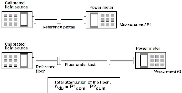
The insertion loss technique is a non destructive method to measure the attenuation across a fiber, a passive component or an optical link. With the substitution method, the output from a source and a reference fiber is measured directly, then a measurement is realized with the fiber to be measured added to the system. The difference between the two results gives the attenuation of the fiber.
Insertion loss and cut back measurements
The cut back technique is the most accurate measurement, but is also destructive, and cannot be applied in the field. This is the reason why it is not used during installation and maintenance. Testing with the cutback method requires first measuring attenuation of the length of fiber under test, then cutting back a part of the length from the source end, and measuring attenuation of this part as a reference, and then substracting the two values: the result gives the attenuation of the cut fiber.
The purpose of the first or "reference" measurement is to cancel out as far as possible the losses caused by the various patch cables.
 |
| Use of Optical Power Meter |
Significant variations may occur in attenuation measurements if precautions are not taken with the injection conditions.
Transmitted and received optical power are only measured with an optical power meter. For transmitted power, the power meter is connected directly to the optical transmitter’s output.
In the case of received power, the optical transmitter is connected to the fiber system and then the power level is read with the power meter from the fiber cable at the point where the optical receiver should be.
Optical Power meter / light source combinations (also defined as loss test sets) measure cable continuity and cable attenuation.
Link losses are sometimes measured in each direction and averaged to improve confidence in the measurements.


1 Comments
Very good post
ReplyDelete