Polarization Mode Dispersion (PMD) testing is becoming a requirement when the transmission bit rate per channel rises or with the increase of the corresponding distance. It appears that the measurement shall be at least performed when the bit rate is equal or higher than 10 Gb/s. However, for fibers older than 1996 or for some applications, such as analog cable TV applications, lower transmission bit rates will be affected by Polarization Mode Dispersion (PMD).
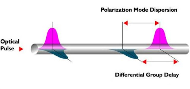
PMD (Polarization Mode Dispersion) is the differential arrival time of the different polarization components of an input light pulse, transmitted by an optical fiber. This light pulse can always be decomposed into pairs of orthogonal polarization modes. These polarization modes propagate at different speeds according to a slow and fast axis induced by the birefringence of the fiber.
Causes of PMD (Polarization Mode Dispersion)
A light pulse transmitted through a “uniform,” Highly Birefringent (HiBi) or polarization maintaining fiber could be defined as the decomposition of the pulse into 2 orthogonal pulses (see figure 1) travelling at different, but constant speed.
However, in telecommunication optical fibers, birefringence levels and principal axis are not uniform over the total link, and could be considered as the result of HiBi fibers randomly coupled together.. As a consequence, there is a polarization mode coupling between the fast and slow local PSPs.. This is called a strong mode coupling. Nevertheless, the fiber still exhibits two PSPs and a DGD at one given wavelength.
 |
| PMD details |
PMD (Polarization Mode Dispersion) because of Bi-refringence
Optical fibers are slightly birefringent. Birefringence is a default of material (e.g. optical fiber) where the effective index of refraction varies with the polarization state of the input light.
The main causes of this bi-refringence are non-perfect concentricity and in homogeneity of the optical fiber in manufacturing design, as well as external stresses applied on the fiber cabling, such as bends, or twist.
 |
| PMD because of Bi-refringence |
PMD (Polarization Mode Dispersion) because of Differential Group Delay
In a single mode fiber, light is guided through the whole core and in a part of the cladding (referring to Mode field diameter), so that there is only a single propagation mode. However, due to birenfringence, the propagation mode is degenerated into two orthogonal modes, defining the two Principal States of Polarization (PSPs). These two PSPs travel at different speeds. |
| PMD because of differential group delay |
The arrival time difference at the output of the media (fiber) is called the Differential Group Delay (DGD) [Δτ (ps)].
 |
| PMD HiBi fiber |
One commonly accepted parameter used to characterize the PMD delay is the mean DGD across a certain wavelength range (Δτ), and is expressed in [ps].
Mean DGD = (Δτ)l
The mean DGD is proportional to the square root of the length of the fiber. If the mean DGD is doubled, the fiber length must be increased by a factor of four.
The PMD coefficient, Δτc [ps/√km], is used to express the PMD delay as a function of the fiber length. Δτ = Δτc × √L ; where L is length of the fiber.
The PMD is defined, then, using up to four main parameters:
➽PMD delay [ps] or mean DGD
➽PMD coefficient [ps/√km]
➽Second order PMD delay or DGD2 [ps/nm]
➽Second order PMD coefficient or PMD2, [ps/(nm × km)]
What is Second Order Polarization Mode Dispersion PMD
The second order PMD describes how polarization induced delay, varies with wavelength,. It provides the indication of the wavelength dependency of the PMD delay.
There are two contributions:
➽Rate of change of DGD vs Wavelength
➽It describes the change of direction of PSPs
Second order PMD has to be added to chromatic dispersion figures, further limiting the CD constraints.In fact, only very high speed (≥ 40 Gb/s) transmission systems are affected by the second order PMD.
How can decreases the Polarization Mode Dispersion PMD
➽Better fiber manufacturing control (fiber geometry)
➽PMD compensation modules
PMD is more an issues for old G.652 fibers (<1996) than newer G.652, G.653, G.655 fibers.
If the maximum PMD delay is known, the maximum admissible fiber length can be deduced.
The statistical character of the PMD is taken into account where defining the maximum tolerable PMD delay as 10% of the bit length TB for a system, without disturbing the network performance by more than 1 dB loss, at 1550 nm,
Polarization Mode Dispersion PMD measurement will be required-
As a summary, the main circumstances in which PMD measurement will be required are:
➽Qualification during fiber manufacturing
➽Qualification during cable manufacturing
➽Installation of new fiber networks, for 10 Gb/s bit rate or higher.
➽Installation of ultra long haul networks at 2.5 Gb/s or higher
➽Upgrade of current networks for 10 Gb/s bit rate or higher
As PMD is a statistical measurement and, because it is sensitive to external environment, it is recommended to perform different measurements at different time intervals so that long term fluctuation of PMD can be monitored, providing better records of the fiber cable.
 |
| PMD Delay measurement |
High Values of Polarization Mode Dispersion PMD
If the PMD measurement is higher than the tolerable limit for a given bit rate, the fiber is classified as “sensitive” to PMD for that particular transmission speed. For a passing PMD result (within the tolerable limit) at a given bit rate, the fiber cannot be classified as “non-PMD sensitive.” Instead, it should be classified as “suitable for the particular transmission rate” at the given time.
Currently, there is no simple and low-cost component that allows for the correction of a link with a high PMD value. Although a number of components are under qualification and development, at this time, very few PMD compensators have been deployed in the field.
Dispersion is clearly important in limiting the distance (or the transmission bit rate) for a given network application. Therefore, several solutions have been developed that allow for the compensation of the effect of PMD on the transmission link, including transmitting over shorter distances, transmitting at lower bit rates per wavelength, using low chirp lasers, using dispersion-managed RZ optical soliton transmission, or using forward error correction (FEC) transmission.
Polarization Mode Dispersion PMD Compensation Techniques
It is particularly difficult to counteract PMD due to its statistical nature and its variation over the time and wavelength. The stochastic nature of PMD is such that reducing the impact of PMD does not necessarily imply the complete cancellation of the effect, rather the reduction of the outage probability due to PMD. This process is called PMD mitigation.
Several PMD compensation techniques have been proposed in the past few years. They can be classified into two main categories:
➤Electrical PMD compensation
➤Optical PMD compensation
Electrical compensation of PMD involves equalizing the electrical signal after the photodiode. This equalization can be implemented in many ways: transversal filter (TF), non-linear decision feedback equalizer (DFE), phase diversity detection. Electrical compensation schemes, in general, are robust and will improve the signal against all kinds of transmission impairments. On the other hand, they do not perform as well as optical PMD compensators and also they require high-speed electronics for better performance.
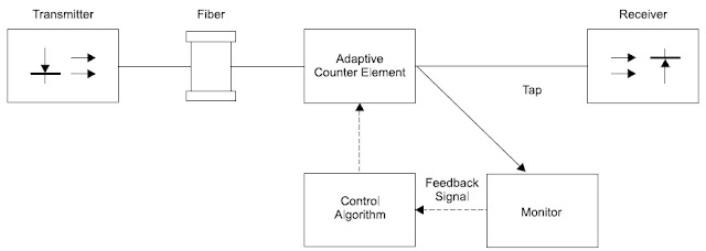
Optical PMD compensation attempts to reduce the total PMD impairment caused by the transmission fiber and the compensator. The block diagram of a general optical PMD compensation scheme is shown. It has an adaptive counter element, a feedback signal, and a control algorithm.
 |
| PMD Compensation |
The adaptive counter element is the core of any PMD compensator. It must be able to counteract PMD impairments and be tunable. The feedback signal is required to provide the PMD information to the controlling algorithm of the compensator.
PMD Test Methods Description
As described in the test and measurement standards, there are different ways of measuring PMD in the field. Only four methods will be described below.
Fixed Analyzer Method (or Wavelength Scanning)
This method requires a broadband polarized source and a polarized (variable) optical spectrum analyzer (OSA).
 |
| PMD Test Method |
From the power fluctuations spectrum, the mean period of the intensity modulation is measured. This is realized by counting the number of extrema , in order to give a mean DGD. Alternatively, a Fourier transform into the time domain will also give a graph, and the RMS DGD value is determined from the standard deviation of the Gaussian curve (for fiber links with strong mode coupling).
Jones Matrix Eigenanalysis (JME) (or Stokes Parameter Evaluation)
This method requires a tunable narrowband source with three linear polarizers and a polarimeter
 |
| Jones Matrix Eigenanalysis (JME) (or Stokes Parameter Evaluation) |
The three known states of polarized light enable the polarimeter to obtain the Jones matrix. The Jones matrix values at pairs of adjacent wavelengths provide the DGD value. The PMD is then calculated by simply averaging the obtained DGD values over the wavelengths.
Interferometry: Generalized Method (GINTY)
This method requires a broadband polarized source, an interferometer (Mach-Zehnder or Michelson) with a polarization beam splitter, and two polarization scramblers.
 |
| Interferometry: Generalized Method (GINTY) |
For fiber links (usually strong mode coupling), the result is an interferogram with random phases, and the mean DGD value is determined from the standard deviation of the curve. This time, the two signals of the polarization diversity detection allow to removing the contribution of the source auto-correlation peak. It is possible to obtain the interferogram without the central peak thanks to the polarization beam splitter. However the real benefit of this method is only obtained by the use of polarization scramblers, allowing to improving absolute uncertainty of the measurement results.
Interferometry: Traditional Method (TINTY)
This method requires a broadband polarized source and an interferometer (Mach-Zehnder or Michelson).
 |
| Interferometry: Traditional Method (TINTY) |
For fiber links (usually strong mode coupling), the result is an interferogram with random phases, and the mean DGD value is determined from the standard deviation of its curve. Nevertheless, the fringe envelopes obtained are a combination of two functions. An algorithm must be used to try to remove the central auto correlation peak which contains no PMD information.


1 Comments
BF6A7411E9
ReplyDeleteTakipçi Satın Al
M3u Listesi
Para Kazandıran Oyunlar
Pasha Fencer Hediye Kodu
101 Okey Vip Hediye Kodu