Ethernet Turn-up Tests
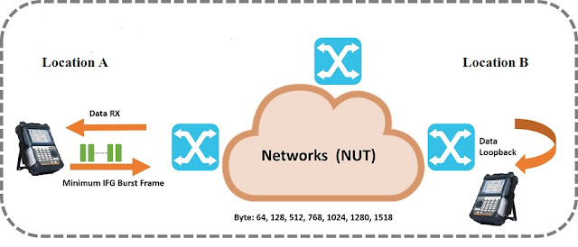
NOTE: You MUST have a far end loop for the RFC2544 test to work.
 |
| Test Setup |
STEP 1 – Setup Test Set for Traffic Generation
The first step to setting up the RFC2544 test is getting the link up and defining any frame addressing. For both 10/100Mbps and GIGE you will need to get the link up and running by setting the LINK INIT portion of the SETUP button. Make sure that AUTO NEGOTIATION and FLOW CONTROL are set to match the network element and card you are testing against.
All the Network Elements must have same settings including the configuration of FST-2802. If auto negotiation is OFF / Disable on NE than on FST-2802 it must be off. In Auto negotiation off condition, the speed (10 / 100 Mbps), the Duplex Mode ( full / half duplex) and Flow control (ON / Enable and Off / Disable) settings must match with FST-2802 and NE.
These are the basic settings of Link initialization only which must be done accurately on NE and FST-2802.
 |
| basic setting |
➤It is HIGLY recommended that flow
control be disabled
in the element and card prior to performing an RFC2544 test. Flow control, by its nature, masks the actual throughput
by buffering the Ethernet frames. This can provide incorrect or inconsistent test results.
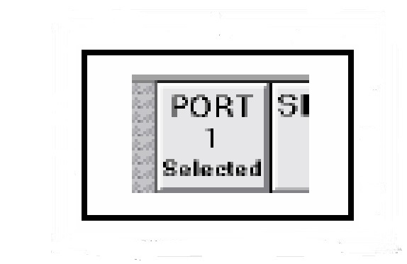
➤If you have a dual port FST-2802 you will need to select PORT 1 or PORT 2 for each of the above tests. On the top right side of the test set you will see either icon that states either PORT 1 or PORT 2 is selected. |
| PORT 1 or PORT 2 |
After the link is up, go back to the SETUP button and select the TX PROFILE button.
 |
| screen allowing the overall traffic setup |
For RFC2544 testing: ➤TX PROFILE – Set this to LP
➤TX PAYLOAD – Set this to ACTERNA
➤DA TYPE – Set this to UNICAST
➤DA ADDRESS – This is grayed out – test set will detect it
➤FRAME – Check the element and card to see the frame type the card will accept. If in doubt try the 802.3 setting first.
➤VLAN TAG – If the circuit requires a VLAN ID, set it here. If no VLAN ID is required, turn the VLAN TAG setting to NON-TAGGED
➤FRAME LENGTH – This setting is not used by RFC2544. Frame sizes will be
Set later in this section.
On the top of the screen when terminating a 10/100 Ethernet – Layer 2 TRAFFIC or
1GIG Ethernet – Layer 2 TRAFFIC, the RFC2544 button will be available:

The RFC2544 test configuration screen will come up. If this is the first time using the
RFC2544 test, the following window will be shown:
 |
| Tesr Configuration |
Select the NEW button to move forward. NOTE: There may be other test set ups that have been saved in the SELECT TEST CONFIGURATION window. You may select an existing test and chose MODIFY instead of NEW.
STEP 4 – Naming Test
Name the RFC2544 test. This name will appear in the test configuration screen for future reference.
Name the RFC2544 test. This name will appear in the test configuration screen for future reference.
This screen gives basic instructions on how to navigate through the RFC2544 set up.
STEP 6 – Frame Sizes
The RFC2544 test makes the throughput, latency, and frame loss measurements using a range of frame sizes. The user can select as little as one frame or as many as all of the frames listed.
 |
| frame loss measurements |
This step allows the user to select the individual results that the RFC2544 test will Calculate. There are 4 options – Throughput, Latency, Frame Loss, and Back to Back Frames tests.
Throughput Test – This test will determine the maximum rate of the circuit without errors. Many Ethernet circuits will be purchases at a rate that is less than the interface rate (e.g. 600meg out of 1 GIG interface). This test will determine what the circuit is provisioned for.
Latency Test – This test will determine the round trip delay for the circuit. The one way latency can be approximated by dividing this result by 2
Frame Loss Rate Test – This test will determine the frame loss at the rate determined by the throughput test. If lost frames are detected the test will continue to reduce the speed of traffic until it identifies that rate which zero frames are lost.
 |
| RFC2544 test will Calculate |
This screen allows the user to pre set the maximum bandwidth for the throughput, latency, and frame loss test. By setting this value close to and slightly above the provisioned rate, the time of the overall test can be reduced.
 |
STEP 8 – Maximum Bandwidth
|
The test set will run the throughput test for the each frame size defined in the frame sizes
screen for
a specific amount of time before declaring a valid maximum throughput rate.
We recommend that this time be set for 20 seconds
STEP 10 – Latency Time
The test set will run the latency test the each frame size defined in the frame sizes screen for the amount of time defined by this set up parameter at the rate determined by the throughput test. It is recommended that this time be set to 20 seconds. |
| Time be set for 20 seconds |
 |
| Time be set to 20 seconds. |
As with throughput and latency tests, the test set will perform a detailed frame loss analysis for a specified period of time for each frame size. We recommend that this be set to 20 seconds.
 |
| This be set to 20 seconds |
The frame loss granularity is the level of detail the frame loss test will use to identify the
bandwidth with zero frame loss. We recommend that this be set to 1% so that the bandwidth of
zero frame loss will be determined to
the nearest percent.
 |
| This be set to 1% |
Step 13: Step Run


 Upon completion of this last step, the RFC test will begin running.
NOTE: If you have turned the back to back frames test on in step 6, you will have to set up this test prior to the RFC test run. It is recommended that you do not run the back to back frames test on the circuit. |
| RFC test will begin running |
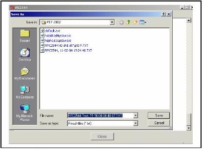
At the completion of the RFC2544 test the user will be prompted to save the test results. These results are saved in the form of a .txt file and can be open using any word processing program. The files are initially stored on the Z: drive of the test set under the FST-2802 directory.
 |
| Completion of the RFC2544 test |


0 Comments